

2 Patch functions reference
This part of the Sim-POV documentation describes the extensions of the POV-Ray scene description language. It is meant to be a reference of these functions but does not give very detailed information on how to use them.
2.1 The simulation settings
This patch introduces a new block in the
global_settings{} section of the POV-Ray scene file.
The complete syntax description of this block is:
MECHSIM:
    mechsim { [MECHSIM_ITEMS...] }
MECHSIM_ITEM:
    method INTEGER | gravity VECTOR | time_step FLOAT |
    step_count INTEGER | time FLOAT |
    environment { ENVIRONMENT_DEFINITION [ENVIRONMENT_ITEMS...] } |
    collision { COLLISION_TOGGLE [COLLISION_ITEMS...] } |
    topology { [GROUP_DEFINITIONS...] [TOPOLOGY_ITEMS...]
               [save_file FILE_NAME] }
ENVIRONMENT_DEFINITION:
    function [(IDENT_LIST)] { FUNCTION_ITEMS } | object OBJECT
ENVIRONMENT_ITEM:
    stiffness FLOAT | damping FLOAT | friction FLOAT [, FLOAT] |
    method INTEGER
COLLISION_TOGGLE:
    [INT_MASS_MASS, [, INT_MASS_FACE]]
COLLISION_ITEM:
    stiffness FLOAT | damping FLOAT | friction FLOAT [, FLOAT]
GROUP_DEFINITION:
    group [(INT_GROUP_INDEX)] { TOPOLOGY_ITEMS... }
TOPOLOGY_ITEM:
    mass { V_POSITION, V_VELOCITY, F_RADIUS
           mass FLOAT | density FLOAT [fixed BOOL] } |
    connection { INDEX1, INDEX2 [stiffness FLOAT] [damping FLOAT]
                 [length FLOAT] } |
    face { INDEX1, INDEX2, INDEX3 } |
    load_file FILE_NAME
2.1.1 The general settings
Some general parameters can be given in the top level of the
mechsim{} section.
The default values are:
method             : 1
gravity            : <0, 0, 0>
time_step          : 0.1
step_count         : 10
2.1.1.1 method
Selects the integration method used for solving the equations of movement.
Possible values are:
- 1 (
MECHSIM_METHOD_EULER) simple forward euler integration method - 2 (
MECHSIM_METHOD_HEUN) second order (heun) integration method - 4 (
MECHSIM_METHOD_GRADIENT) gradient descent method
Method 1 is a first order integration method also known as explicit euler method. With the differential equations of movement written as:
dy/dt = f(t, y)
y being the state of the system (positions and velocities)
and the initial conditions y(t0)=y0 the euler method can
be written as:
yn+1 = yn + h*f(tn, yn)
Method 2 is a second order integration method known as Heun's method. It's formula is:
k1 = f(tn, yn)

k2 = f(tn + h, yn + h*k1)

yn+1 = yn + (h/2)*(k1 + k2)
2.1.1.2 gravity
Applies an overall constant gravitational force to all masses.
A vector is expected, the unit is m/s².
Standard earth gravity (with y=up coordinates) is:
gravity <0, -9.81, 0>
2.1.1.3 simulation stepping
All simulation methods use discrete time steps for calculating the simulation. There are three parameters to steer this but only two are needed to correctly define the stepping. The formula for calculating the third is:
Step_Count = Time / Time_Step
2.1.2 The environments
Environments are shapes the simulated masses are supposed to interact
with. Several of them can be created with environment{} blocks.
2.1.2.1 The environment definition
An environment is defined either by a user defined function or an object. If both are given the function is preferred.
Apart from the default parameters (x, y and z) the function can have a fourth parameter supplying a time index. It's value changes from 0 to 1 during the simulation. This way moving environment objects can be simulated.
Example:
#declare fn_Env=function(x, y, z, tim) { z-tim }
global_settings {
...
mechsim {
...
environment {
function(x, y, z, tim) { fn_Env(x, y, z, tim) }
...
}
}
}
2.1.2.2 The environment properties
There are three parameters defining the properties of the environment:
stiffnessThe elasticity parameter of the surface. The unit isN/morkg/s².dampingDepending on the environment calculation method (see below) this is either a diminishing factor (<1) applied to the mass velocities at each collision or a damping constant (unitkg/s)frictionThe friction factor controls the amount of friction during collisions. An optional second parameter, the friction excess value should usually be slightly larger than 1 and causes the friction to occur already slightly above the surface. This can be helpful to obtain realistic results.
2.1.2.3 The environment calculation method
There are currently two methods how the environment collisions can be calculated:
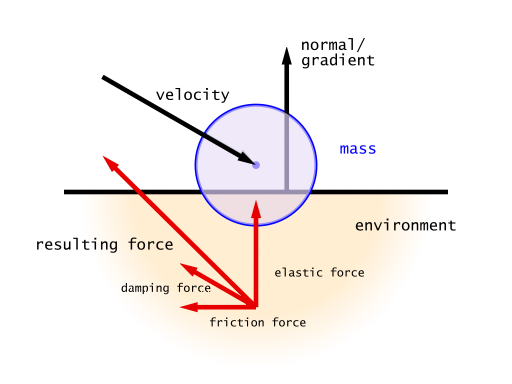
Method 1 (MECHSIM_ENV_METHOD_FORCE) is force based. When a
mass collides with the environment a force is applied in direction of the
function gradient (with function based environments) or the surface normal
(with objects). The stiffness, damping and
friction parameters influence this force. friction
defines the ratio between the tangential force and the normal force.
Method 2 (MECHSIM_ENV_METHOD_IMPACT) is based on impact laws.
The velocity is inverted at the surface and diminished by the
damping factor in normal direction and by the friction
value in tangential direction. stiffness does not have any
influence in this case.

Since this method directly modifies the velocity rather than applying forces it should only be used with the first order (euler) integration method.
With the gradient descent simulation method the method parameter does not have any effect.
2.1.3 The collision settings
The collisions referred to here are not environment collisions but collisions between the simulation elements. Since detecting this kind of collision is quite computationally intensive it is turned off by default.
With two numbers at the beginning of the collision{} section
collision can be toggled for both mass-mass-collisions and mass-face-collisions.
Both parameters are optional, the meaning of the possible values is:
- 0 (
MECHSIM_COLLISION_NONE) No collisions of this kind are calculated. - 1 (
MECHSIM_COLLISION_ALL) Collisions between all simulation elements are calculated. - 2 (
MECHSIM_COLLISION_GROUP) Only collisions between elements of different groups are calculated.

Internal collisions are always calculated with forces. The same three parameters like in the environment settings can be used to specify the properties
stiffnessThe elasticity parameter of the surface. The unit isN/morkg/s².dampingA damping constant (unitkg/s)frictionThe friction factor controls the amount of friction during collisions. An optional second parameter, the friction excess value should usually be slightly larger than 1 and causes the friction to occur already slightly before the collision. This can be helpful to obtain realistic results.
An example for a complete collision{} section:
global_settings {
...
mechsim {
...
collision {
2, /* mass-mass collisions between elements of different groups */
0 /* no mass-face collisions */
stiffness 20000
damping 4000
friction 0.2, 1.01
}
}
}
2.1.4 The topology
The topology{} section is the central part of the whole simulation
settings. Here the simulation elements, their positions and properties, can be
defined.
2.1.4.1 The topology items
There are three topology items: masses, connections and faces. Each of them has several parameters that can be set.
The mass block defines a point mass. These are the central elements
of the simulation. Their movement is calculated by the simulation system.

The mass block contains the following elements:
- The first item is a vector specifying the position of them mass
(unit:
m). - The second item, also a vector, represents the velocity of them mass
(unit:
m/s). - The third item is a float standing for the radius of the mass (unit:
m). This radius is only used in collision calculations. Otherwise the mass behaves as a point mass.
In addition either the mass (unit: kg) or the
density (unit: kg/m³) of the element has to be given.
If density is specified the resulting mass is calculated
automatically. An optional boolean parameter (fixed)
prevents the mass from moving if set to true.
A complete example for a mass definition:
mass {
<0, 0, 1>, /* position */
<1, 0, 0>, /* velocity */
0.1 /* radius */
density 600
// mass 2
// fixed true
}
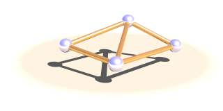
The connection block defines a connection between two point masses.
It can have elastic and dissipative properties.
The first two elements of this block are integer numbers specifying the indices of the masses to connect.
There are three optional parameters: The stiffness value specifies
the elasticity of the connection (unit N/m or kg/s²).
damping the velocity proportional damping factor (unit kg/s).
The default value for both of these is zero. The third parameter allows to specify
a relaxed length of the connection. If it is not specified the distance of the two
masses is used for this property.
A complete example for a connection definition:
global_settings {
...
mechsim {
...
topology {
mass { ... } /* mass with index 0 */
mass { ... } /* mass with index 1 */
connection {
0, /* index of the first mass */
1 /* index of the second mass */
stiffness 10000
damping 2000
// length 0.5
}
...
}
}
}
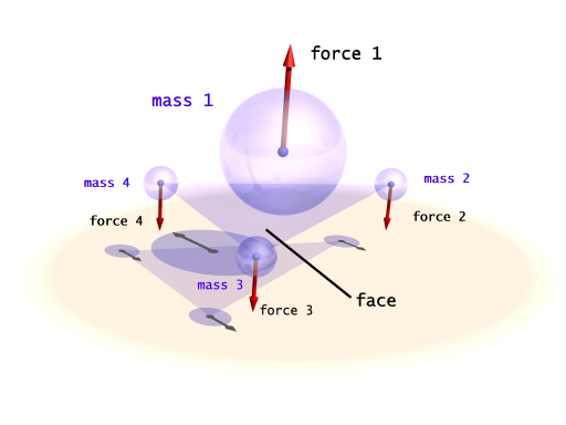
The face block defines a triangular face between three point masses.
It is used for collision calculations and can be useful for
generating a mesh from the simulation data for display.

There are three integer numbers in the block, the indices of the masses forming the face.
A complete example for a face definition:
global_settings {
...
mechsim {
...
topology {
mass { ... } /* mass with index 0 */
mass { ... } /* mass with index 1 */
mass { ... } /* mass with index 2 */
face {
0, /* index of the first mass */
1, /* index of the second mass */
2 /* index of the third mass */
}
...
}
}
}
2.1.4.2 grouping elements
Simulation elements can be categorized into groups. The main purpose of this
is to speed up collision tests. The group keyword can be followed by
an integer number in parentheses to explicitly specify the group. Otherwise
the group index is determined automatically.
Example:
global_settings {
...
mechsim {
...
topology {
mass { ... } /* these elements are group index 0 */
...
group {
mass { ... } /* these elements are group index 1 */
}
group {
mass { ... } /* these elements are group index 2 */
}
group (1) {
mass { ... } /* these elements are group index 1 */
}
...
}
}
}
2.1.4.3 saving and loading topology data
The topology data can be written to and loaded from files. The format of these files is described in section 2.3.
save_file can only be added to the main topology{}
block. It saves the complete data after the simulation to the specified file.
load_file can be placed anywhere in the topology{}
section. If placed in a group the elements in the file are added to that group.
Otherwise they are are placed in groups according to group index information in
the file.
The same file name can be specified for both loading and saving the data. This is especially useful for animation when the following frame simulation should start with the result of the last frame:
global_settings {
...
mechsim {
...
topology {
load_file "mechsim_data.dat"
save_file "mechsim_data.dat"
}
}
}
2.2 Accessing simulation data
The whole simulation data can be accessed anywhere in the POV-Script. This is achieved by adding new float/vector functions:
FLOAT_FUNCTION:
    ... | mechsim : MECHSIM_ELEMENTS
MECHSIM_ELEMENTS:
    mass_count | connection_count | face_count |
    mass( INTEGER ) : MASS_FLOAT_ELEMENT |
    connection( INTEGER ) : CONNECTION_FLOAT_ELEMENT |
    face( INTEGER ) : FACE_FLOAT_ELEMENT
MASS_FLOAT_ELEMENT:
    radius | mass
CONNECTION_FLOAT_ELEMENT:
    index1 | index2 | length | stiffness | damping
FACE_FLOAT_ELEMENT:
    index1 | index2 | index3

VECTOR_FUNCTION:
    ... | mechsim : MECHSIM_ELEMENTS
MECHSIM_ELEMENTS:
    mass( INTEGER ) : MASS_VECTOR_ELEMENT
MASS_VECTOR_ELEMENT:
    position | velocity
These elements correspond to those set in the
mechsim{} block in global_settings{}. The
mass position and velocity are the ones that are modified during
simulation. The mass_count connection_count
and face_count values are especially useful inside
the mechsim{} block to determine the current index:
global_settings {
...
mechsim {
...
topology {
/* part 1 */
mass { ... }
mass { ... }
connection { ... }
...
#declare Start_Mass_Part2=mechsim:mass_count;
#declare Start_Connection_Part2=mechsim:connection_count;
/* part 2 */
mass { ... }
mass { ... }
connection { ... }
...
}
}
}
The Start_Mass_Part2 and Start_Connection_Part2
variables can later be used to display the different parts of the simulation
in different forms.
2.3 The simulation data file format
The file format used by the load_file and save_file
options is a text format compatible to the POV-Ray #read and
#write directives.
The different fields in the file (referred to as 'elements' here) are separated by commas (,) and each contain either a string, an integer or float value or a vector.
The first element is a four character string ('MSIM') identifying the Sim-POV format. The second element is an integer number specifying the subformat of the file. This value is always '2' in files written by Sim-POV. There is no way influencing the format Sim-POV writes right now.
The following three integer numbers are the numbers of masses, connections and faces in the file. After them follows the data of all masses, connections and faces in that order.
For each mass there are the following elements:
- The position (vector), unit:
m - The velocity (vector), unit:
m/s - The mass (float), unit:
kg - The radius (float), unit:
m - A flag (integer) currently only containing the
fixedvalue. This flag could contain other boolean values in the future (connected with logical OR) so it should be tested accordingly (if (flag & 1)) - The group index (integer)
For each connection:
- The index of the first mass (integer)
- The index of the second mass (integer)
- The relaxed length (float), unit:
m - The stiffness (float), unit:
N/morkg/s² - The damping constant (float), unit:
kg/s - The group index (integer)
For each face:
- The index of the first mass (integer)
- The index of the second mass (integer)
- The index of the third mass (integer)
- The group index (integer)
The files written by Sim-POV contain a line break after the subformat value, the mass count, connection count and face count value and after each mass, connection and face.
A short sample file looks like this:
MSIM, 2,
3,
3,
1,
<-2, -2, 0>, <0, 0, 0>, 2.0, 0.05, 0, 0,
<2, -2, 0>, <0, 0, 0>, 2.0, 0.05, 0, 0,
<0, 2, 1>, <0, 0, 0>, 2.0, 0.05, 0, 0,
0, 1, 0.8, 12000, 6000, 0,
1, 2, 0.8, 12000, 6000, 0,
0, 2, 0.8, 12000, 6000, 0,
0, 1, 2, 0,