In this second part of my short series of blog posts on using line signatures in digital maps (see first part) i want to introduce some work i had partly already done some time ago at the Karlsruhe Hack Weekend to add support for some additional line features through line patterns to the AC-Style, as well as adding differentiated rendering of barriers.
Parts of these changes are concerning tags which are widely and consistently used in OpenStreetMap and therefore their rendering is of current practical use. Others are more proactive design of things not yet widely mapped in OpenStreetMap so far, which i show here for demonstrating what could be part of a feature rich map and as test cases to demonstrate certain techniques.
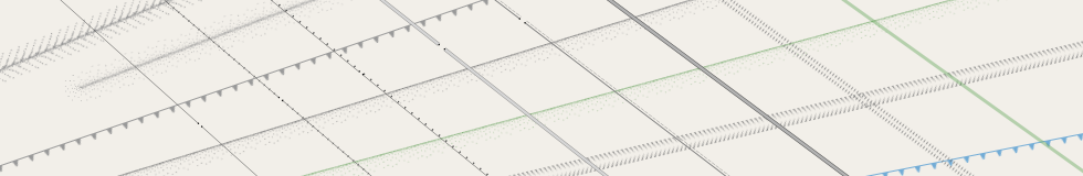
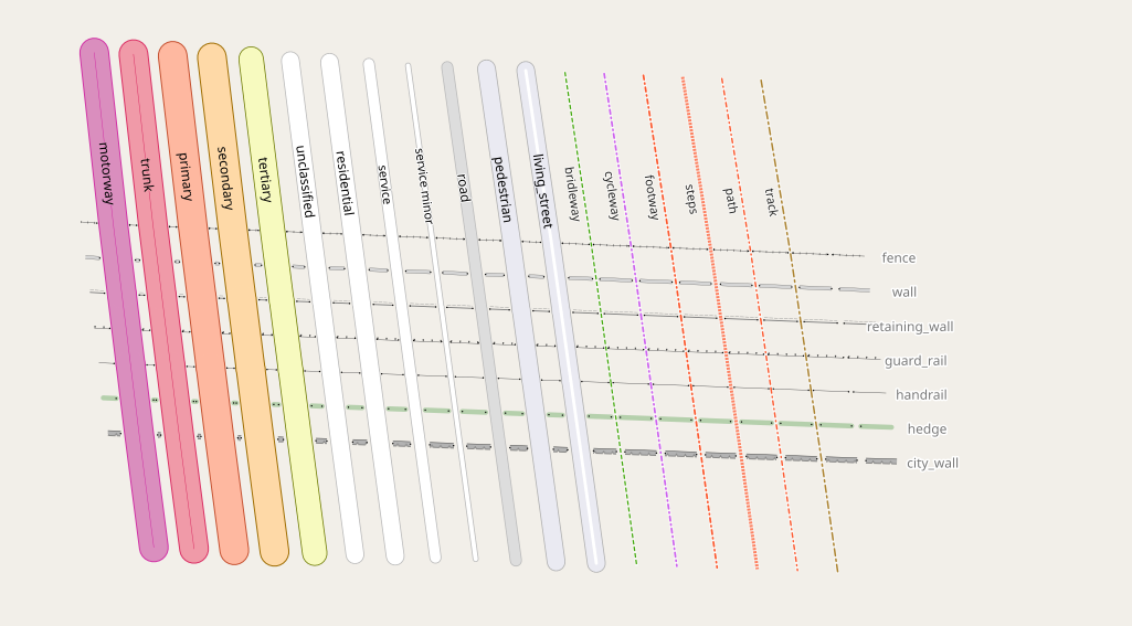
Traditionally, line patterns are used in OSM-Carto for cliffs (natural=cliff) and embankments (man_made=embankments) as well as more recently also for ridges (natural=ridge) and aretes (natural=arete). Most linear barriers (barrier=chain, barrier=ditch, barrier=fence, barrier=guard_rail, barrier=handrail, barrier=retaining_wall, barrier=wall) are uniformly rendered with a simple gray line, only barrier=hedge and barrier=city_wall/historic=citywalls have their own, more specific line signatures.

Natural lines and barrier line signatures in OSM-Carto at z18
In the AC-Style i had already added support for implicit embankments (embankment=yes/cutting=yes) on roads/waterways (see here) and – as part of my tree rendering work – differentiated rendering of hedges. I had also added support for rendering mapped entrances on barriers (barrier=entrance) – but i have not discussed this feature here so far, so i will quickly discuss this at the end of this post as well.
Additional and improved natural linear features
The starting point for my work at the Hack Weekend on the patterns was that i had previously added support for rendering natural=earth_bank – using the line pattern for cliffs in a brown color. But i was never satisfied with that because (a) introducing yet another color is generally a poor choice for adding a new feature, given how confusingly many colors there are already in use (and brown lines being otherwise used for track roads) and (b) because the differentiation by color is misleading as it implies a differentiation mainly by surface material – while the tag natural=earth_bank is used much more broadly in terms of surface topography than natural=cliff (which is exclusively for vertical or near vertical structures) and a good design should reflect that.
What i did instead was to use an asymmetric version of the ridge pattern, which is meant to imply that natural=earth_bank and natural=cliff form a bit of a pair, in a fashion similar to natural=ridge and natural=arete. I did make use of color by differentiating earth_bank=grassy_steep_slope with a green instead of a gray color.
I also added support for rendering natural=gully with a directed symmetric pattern.
So much for new linear natural features. What you can also see in the above sample rendering is that i added special rendering of unconnected line starts and ends for natural=ridge and of line starts for natural=gully. There is no built-in support for that, so this is manual work using point symbolizers. Line starts are relatively easy – you just have to design a half-circular closing for the line pattern on the left side and render it with the proper orientation on the starting point. Line ends are more difficult because the pattern can – due to the way it is rendered by Mapnik – end on any phase of the pattern image and therefore will not precisely match a static line end cap image. For a fine structure pattern, like the one used for ridges, that is not much of a problem but for other patterns different solutions would need to be employed.
As i mentioned in the first part of the blog post, the way line patterns in Mapnik work is by piecewise linear mapping of the pattern image onto the linestring. This rules out anything like rounded line joins. The problem is that with many pattern images corners in the linestring at the wrong location can lead to odd discontinuities. You can widely observe this with the cliff pattern where, when a dent of the cliff pattern is directly located at a corner of the cliff, it frequently produces artefacts.
What you can do to mitigate this problem is to (a) offset the curve towards the center of the pattern rather than to center the pattern image on the centerline (like it is done in OSM-Carto) in case of asymmetric patterns like for cliffs and (b) minimally round the corners by using ST_OffsetCurve(). This avoids individual sharp corners. It does not allow for true round line joins, but it can help avoiding the most severe artefacts.
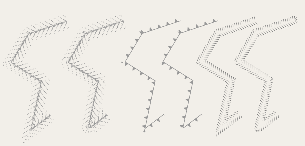
Plain line pattern (left) and with line join tuning and artefact reduction techniques (right) – double resolution version
Another approach that can help with getting more harmonic corner rendering is to split the line signature into several line patterns and render them independently. The less wide the pattern image is, the less do corners in the line lead to disruptions of the pattern image. This is the approach i used for natural=gully where the left and right side of the line signature are rendered independently. This means that the left and right side are, in general, not in sync along the course of the line. How much of a problem that is depends on the line signature used.
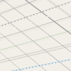
Another problem with line patterns are junctions between several lines. Again – Mapnik does not have any built-in support for that. The patterns for natural=ridge and natural=arete were specifically designed to work gracefully in such situations but this does not apply equally to natural=gully where junctions are a common occurrence. Therefore, cutting the lines with the connecting geometries in a similar way as i have done with sidewalks and implicit embankments is required.
Junctions with line pattern – rendered as is for ridge and arete, with manual management based on separate rendering of left and right side for gully – double resolution version
Differentiated rendering of barriers
The other group of linear features i have looked at are constructed barriers tagged with barrier=*. Here i implemented the following:
- The differentiated rendering of
barrier=fence,barrier=guard_rail,barrier=wall,barrier=retaining_wallandbarrier=ditchat the higher zoom levels - The differentiated rendering of
barrier=wallandbarrier=retaining_wallwithheight<=0.5- because they are in practical meaning substantially different from higher walls. - The ground unit rendering of
barrier=wall,barrier=retaining_wall,barrier=ditchandbarrier=city_wall/historic=citywallsaccording to taggedwidth=*
Here is how this looks like:
The way variable width rendering is implemented differs between the different barrier types. barrier=wall and barrier=retaining_wall use a combination of different solid and dashed lines. barrier=city_wall/historic=citywalls in addition uses, for the distinct rendering of the outside face of the wall, a line pattern. And barrier=ditch uses a parametrized line pattern. This works somewhat similar to the tree symbols technique - a sequence of line pattern SVGs is generated via script for different line widths based on a parametrized pattern definition in SQL code.
By the way - both barrier=ditch and natural=gully work decently together with a waterway:
Further details
I made some adjustments to the rendering of dykes - which i had already introduced as part of rendering implicit embankments. They are now rendered with a variable width of the line pattern similar to the method used for barrier=ditch. They are also rendered slightly asymmetrically with a wider slope on the right side and a more narrow slope on the left side. Dykes typically have an asymmetric profile with the wider and more gentle slope on the seaward side. Unfortunately, so far no convention is established in OpenStreetMap regarding the directionality of dyke mapping. So this is more a demonstration of what could be done with consistent mapping. For this to work, the line patterns for dykes are rendered separately for both sides, similar to how it is done with natural=gully.
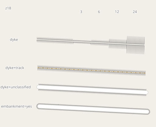
Rendering of dykes with variable width and in comparison to implicit embankments at z18
Of course for wider dykes changes in direction will not look that good. Same for combination with roads/paths with or without implicit embankments.
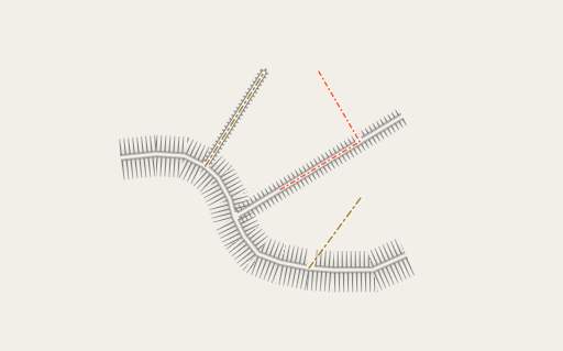
Dyke rendering with context at z18
I promised above that i would quickly discuss the rendering of barrier=entrance - which is not a new feature but has been around in the AC-Style for some time. barrier=entrance is used to map an entrance within an otherwise continuous barrier. In a nutshell: It is similar to barrier=gate, just without the gate. To render this you need to interrupt the rendering of the barrier at the node tagged barrier=entrance. And that interruption needs to be adjusted in width to the drawing width of the road/path crossing the barrier there. In addition i mark the ends of the barrier around the entrance with small dots - making it clearer that this is an explicitly mapped entrance and not a gap in barrier mapping. Here is how this looks like for various types of barriers:
barrier=entrance in combination with various barrier and road types at z19
Finally: I added support for dedicated rendering of natural=cliff with surface=ice. Background for this is that in polar region ice cliffs are a widespread feature, in particular at coasts. The majority of the Antarctic coast is formed by ice cliffs. Here is an example to give you an idea.
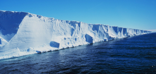
Typical ice cliff coast in the Antarctic
This is not widely mapped explicitly with natural=cliff so far but this would clearly be a significant aspect of more detailed mapping of polar regions.
Here is how the new rendering looks like in typical contexts - both within a glaciated area and at their edge towards the three different colors of waterbodies in the style.
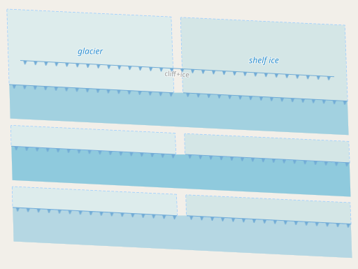
Ice cliffs (natural=cliff + surface=ice) in their expected color contexts at z18
Practical Examples
And here are a few examples with real world data of some of the features discussed.
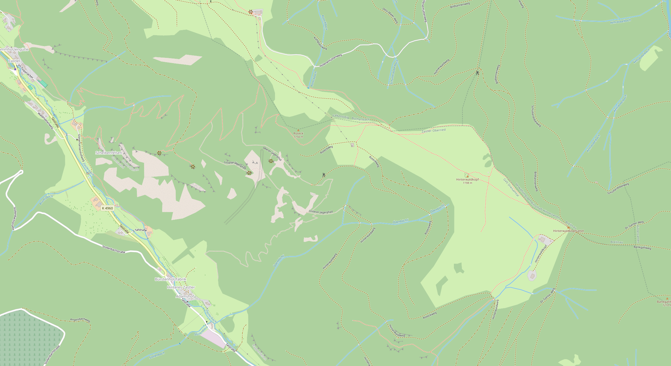
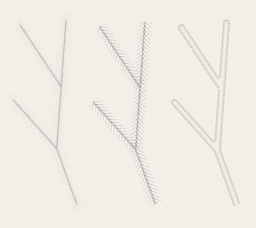
natural=gully at z16
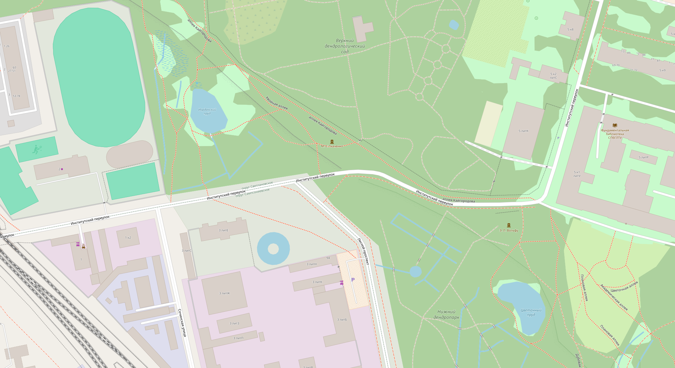
natural=earth_bank and barriers at z18

Barriers at z19
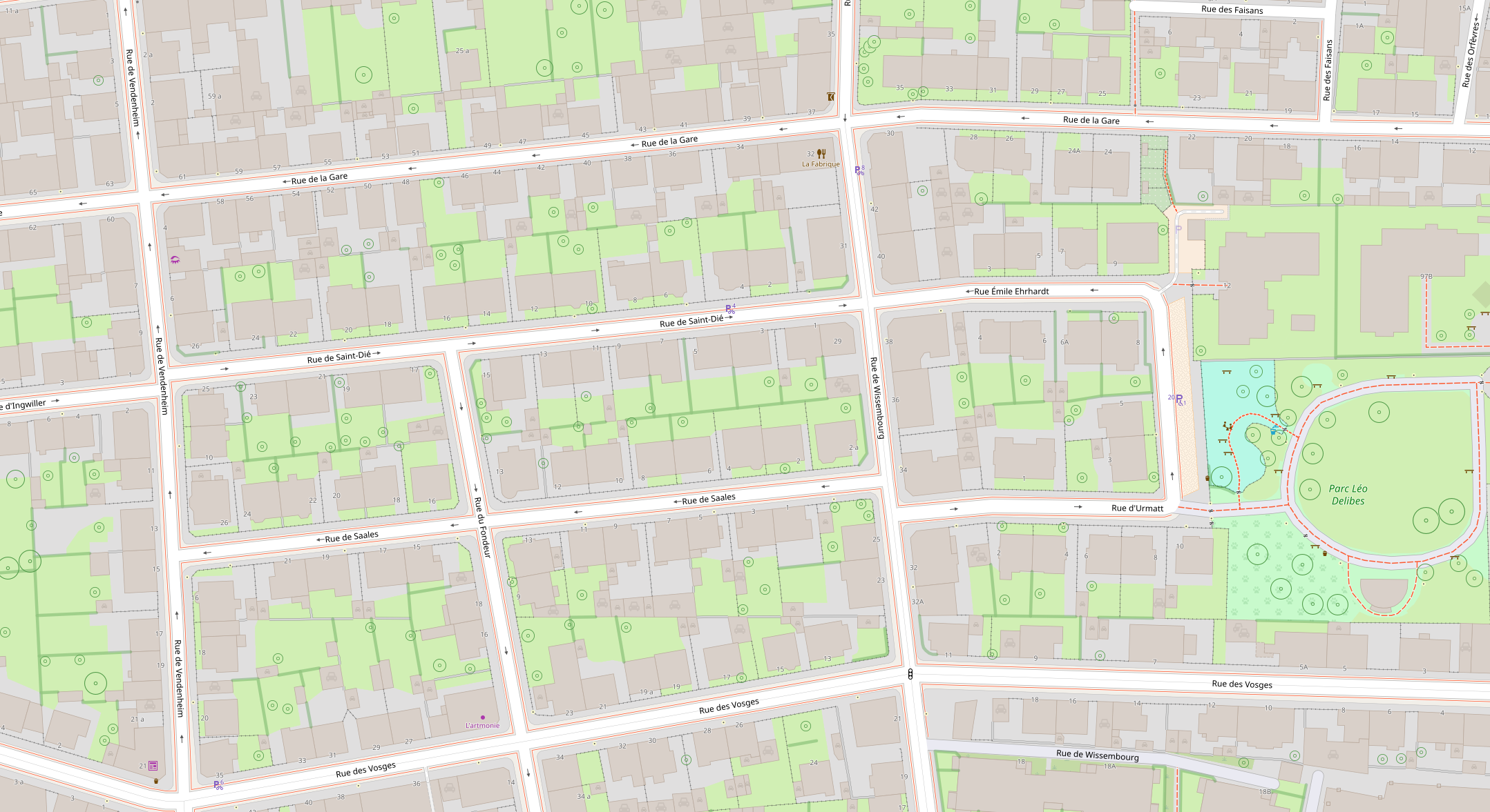
Barriers at z19
Citywalls and other barriers at z19
Implementation notes
Like i already did with the point symbols and the polygon patterns i moved to colorizing the line pattern images via script to allow color adjustments to be applied consistently without manually editing several SVGs. The script doing that (generate_line_patterns.py) also implements the generation of line width sequences for the parametrized line patterns like used for barrier=ditch.
Furthermore, i also added a feature to the scripts processing the symbols and patterns to generate contact sheets. Those can be found in symbols/README.md. Those are not rendered with Mapnik but with ImageMagick so they can both be used for quick visual verification in symbol design and for evaluating issues in Mapnik rendering by providing an independent reference.
Summary and Conclusions
What i showed in this blog post is how line patterns and other means available in Mapnik and CartoCSS can be used to generate complex line signatures beyond the naive use of line patterns, while avoiding to do a fully manual implementation like i did for the trees. I showed various techniques that can be helpful, in particular
- manual drawing of line cap images to supplement a line pattern
- adjusting the centerline location and joins of a line pattern based line to mitigate common artefacts
- splitting a complex line signature into components for better quality rendering of corners
- ground unit rendering in combination with complex line signatures
- techniques for rendering junctions with line patterns
- examples of various ideas for line signature design for different purposes
Still - i hope it also became visible that quality and design possibilities are still massively limited, even when using these techniques, compared to the state of the art in pre-digital map design.
It is only possible to go substantially beyond what i showed here with common map rendering frameworks if you draw things manually on the micro-element level without relying on built-in higher level features from the renderer like line patterns. I took this approach in case of trees and tree rows in the past but i deliberately did not want to go this route here and instead wanted to explore what can be done by using the built-in higher level means.
In the third part i am going to take this a bit further on a specific class of features.
Pingback: weeklyOSM 676 – weekly – semanario – hebdo – 週刊 – týdeník – Wochennotiz – 주간 – tygodnik